
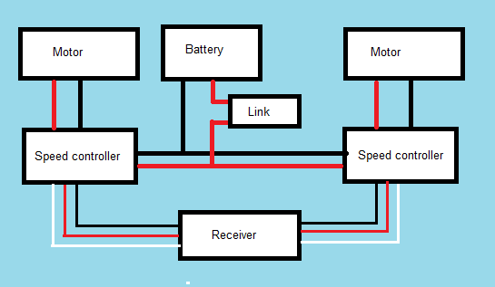
Time for part 2 of our "So You Want To Build A Robot For Robot Wars" blog looking at the insides of a Robot Wars robot. Previously we looked at the batteries and speed controllers. Now we will look at the remainder of our schematic.
Motors
Electric motors are again a topic that we could spend an entire blog discussing but we will look to give you the most important information. The motors we are discussing here are those we will use for a drive system. They tend to have different characteristics from those you would use in a weapon system. We will also focus entirely on DC brushed motor options as the brushless option is still very experimental with some of the most experienced teams and is therefore not recommended for the new builder.
If you are not experienced with the general workings of a DC electric motor then we would highly recommend carrying out your own research on this topic. There are dozens of websites that do a far better job of explaining this than we could do.
Traditional options
In the older series of robot wars the go to motor for 90% of teams was the 24v bosch 750GPA motor. This motor was used in truck refrigeration systems and would produce 750w or roughly 1hp. The motor could have several modifications made to make it battle hardened. Unfortunately this motor is no longer manufactured and finding them is almost impossible although they do pop up from time to time. We would recommend avoiding it simply because replacements are difficult to come by.
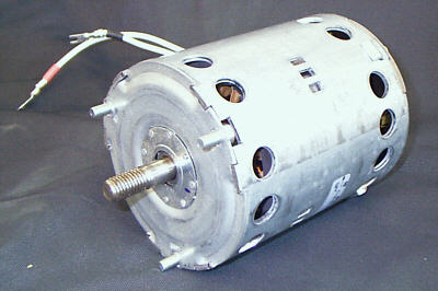
Bosch 750 GPA motor
Another traditional option that is actually still in production is the Iskra 24v 800w motor. These were used by a few teams including Team Typhoon. Slightly smaller than the bosch 750w they were also completely sealed so didn't have to worry about getting dirt inside. They are typically used in hydraulic systems. Again we wouldn't recommend using them these days purely based on the price increases that have seen new versions of this motor cost upwards of £200. There are other more cost effective motors available to the robot builder nowadays.
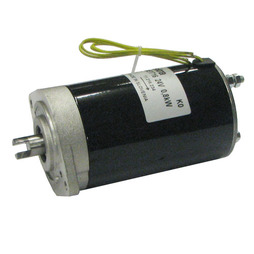
Iskra 800w motor
Other options previously used include wheelchair motors and engine starter motors. Whilst these can be picked up cheaply, we wouldn't recommend using either. Wheelchair motors are typically geared to no more than 4 or 5mph on an 8 to 10 inch wheel. Modern robots need to move much quicker than this around the arena. So the only options are to use exceptionally large wheels like chimera did in the 2016 series or accept that you will be run around by every other machine in the arena. Starter motors draw huge currents and are not designed to be run for more than a few seconds at a time. Speed control on these is therefore exceptionally difficult.
Modern options
There are mainly options available to the modern roboteer although a few require importing from the USA which obviously increases the price a little.
The motors that we use in PP3D are the NPC T64 motor and gearbox (we will look at gearboxes and gearing in a separate post). These are made for wheelchairs however they are designed for use in wheelchairs for bariatric care. This means that they are more powerful and robust than your typical wheelchair motor. They also come in a T74 variant that is slightly more powerful. The T64 version is more than adequate for heavyweight use. There are also a number of bolt on options to connect to the output shaft although be aware that the threads are imperial. Suitable bolts can be found easily on ebay.
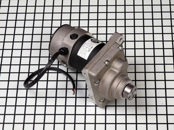
NPC T64 motor and gearbox
Another well used option are the ampflow series of motors. These come in many variants. The main differences in the various models being the type of magnets used in the motors. Some variants use cheaper ferrite based magnets whereas the real expensive powerhouse motors use rare earth neodymium magnets. These are incredibly powerful producing several horsepower in a tiny package however they can get quite pricey and all version require additional gearing. There are bolt on gearboxes available for these from both ampflow and team whyachi which can be handy for a quick set up.
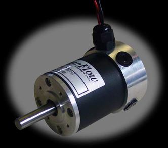
Ampflow motor
If you are on more of a budget and looking for options in the UK then there are a few available. These include 36v 800w and 1000W scooter motors which are available on ebay and can be bought cheaper if you ship them from china although this comes with a longer delivery time. Some teams have been recently buying these to experiment with and have found them to work well. Just make sure you don't get anything below 750w in terms of power rating as it will struggle to move your robot.
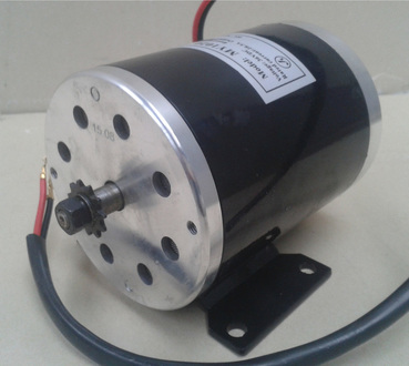
Ebay scooter motor
Another option is from an Italian manufacturer called Movimotor. They have motors available that are essentially drop in replacements in terms of power and fitment as a bosch 750 GPA however they are a bit heavier and again need some battle hardening but have been used in the heavyweight robot Brutus successfully. Movimotor provide a whole range of options so it would be best to contact them directly for specifications and pricing.
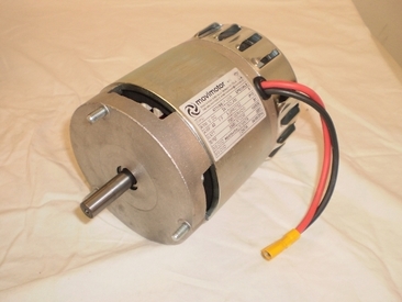
Movimotor
Radio gear
Traditionally roboteers were stuck using the 40Mhz frequency radio band for ground based vehicles. The 40Mhz kit meant that you had to have a huge aerial sticking out the transmitter and robot (obvious when you look at the old fights on youtube) and they were very susceptible to interference. In the old series, radio problems were a major problem for a lot of machines. The old sets were also very expensive with a decent setup costing upwards of £200 plus.
You will have noticed that watching the new series, radio issues were never a problem. This is because we have all switched over to the 2.4Ghz radio frequency. The radio equipment now uses tiny aerials that can be tucked away behind panels and wiring without fear of losing control of your machine. We rarely worry about the location of the receiver in the robot.
There are two parts to your hobby radio gear, the receiver (the bit in the robot) and transmitter (the bit you hold to control the robot). On 2.4Ghz the transmitter and receiver bind to one another so that they will only ever response to each other and not another set.
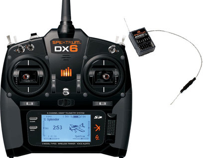
DX6 radio gear from spektrum
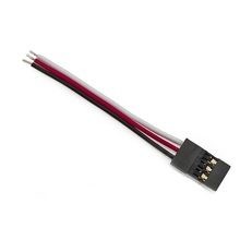
You can see on the receiver on the right in the picture above that there are a series of pins. These pins are the sockets that your speed controller plugs into. From these pins the speed controller gets it's signal to let it know when to drive the motors and by how much. They use a standard servo plug which has three lines, a positive, a negative and a signal line. The colours used for each of these lines can change from manufacturer but they are always the same three connections. In the image below, the negative is black, positive is red and signal is white.
Each set of 3 pins on the transmitter is known as a channel. Each one of these channels corresponds to a control on the transmitter. So for instance, the sticks in the middle each have two possible movements (up and down, left and right). Each of these movements is a channel. So that's 4 channels. You can have extra channels which can correspond to extra switches on the transmitter shoulders. The Dx6 shown in the image above has 6 channels which is more than enough to control a robot and weapon. This is a decent set which won't break the bank but will give you all the functionality you need for most robot designs.
If you have an old 40Mhz or 35Mhz set that you have stashed away then it is possible to upgrade it and use it legally on the 2.4Ghz frequency. There are conversion kits available from frsky which require a bit of soldering inside the transmitter but allow you to use your older equipment. This is what we did for PP3D as we had some old futaba 40Mhz radio gear that was still perfectly usable.
There are dozens of other sets available but the most important thing is that they failsafe when signal is lost. During the tech check that will be carried out on your robot before the competition you will be asked to demonstrate that the robot failsafes by running it's wheels and then turning off the transmitter. It must stop within a few seconds to pass this test. If it doesn't then you won't be allowed to compete. Some cheaper radio sets won't failsafe properly. Best to ask around on the FRA forum if the set you have in mind will be any good.
Removable link
The rules state that each robot MUST incorporate a removable link. This link should remove all power to the robot. It should be removable by hand and without the use of tools.
You will have seen in the latest series that a problem in a few matches was the removable link coming loose. While this may be a frustration for both builder and viewer it highlights a very important fact about the removable link. That when it fails, it fails to a safe condition.
Typical removable links are made from a connector such as the anderson 175A or EC5s. The connector has to take all the current that will pass through the various systems on the robot. For the large spinners this can be many hundreds of amps.
One half of the connector has a loop of wire connected to both terminals in the same connector which gives you a loop of wire you can grab to pull it out. The other half is placed on the positive line (preferably) just after the battery and before the various elements of the robot that use the battery (as shown in the diagram at the start of this post). Placing the loop in completes the circuit and pulling it out kills it disabling the robot.
Anderson 175A connector
There have been a number of individuals on the FRA forum that have suggested a custom link of some description to stop the link falling out. The big issue with this is, if you happen to misplace your link just before your battle (believe me, it happens) then you can still grab another robots link and run your machine as you are running with the same removable link. A strip of duct tape over the link is generally more than good enough to keep the link in place.
If your robot is invertible you have to make sure that the link is accessible regardless of whether it's upside down or not. If you have multiple links, such as one for your drive and another for your weapon system, these have to be located together on the robot so that the crew can deactivate your robot quickly and safely.
If your robot is invertible you have to make sure that the link is accessible regardless of whether it's upside down or not. If you have multiple links, such as one for your drive and another for your weapon system, these have to be located together on the robot so that the crew can deactivate your robot quickly and safely.
That's us come to the end of our basic diagram describing the internals of a basic rammer bot. Hopefully the inner workings make sense as we have described them! If you have any questions, comments or ideas for future blog posts then please put them in the comments below.
We are also running a kick starter to help us with upgrades to PP3D for a second series of Robot Wars. If you have enjoyed our blog then please consider pledging. Any help you can give means a huge amount to the team.
https://www.kickstarter.com/projects/583580427/pp3d-upgrades-for-series-2-of-robot-wars
 RSS Feed
