
We've had a look at some of the internal components that make up a basic rammer robot. You've got a basic idea of what parts you want to use but now you need a chassis to mount them all onto. In this post we are going to look at the design principles that were used traditionally for chassis construction and armour along with the modern principles that have evolved since.
Chassis design is a complex process that requires a good bit of trial and error. The purpose of the chassis is to support all the parts of the robot and allow you to deliver your weapon to the opponent whilst being able to survive the resultant forces that will go back through your robot. The requirements of a flipper differ to a crusher or spinner.
Chassis design is a complex process that requires a good bit of trial and error. The purpose of the chassis is to support all the parts of the robot and allow you to deliver your weapon to the opponent whilst being able to survive the resultant forces that will go back through your robot. The requirements of a flipper differ to a crusher or spinner.
Chassis design
Traditionally chassis design was a mixed affair. The typical method was to construct an inner skeleton from steel box section. Armour panels were bolted on the outside and brackets were welded on the inside to allow motors, gearboxes and weapons to be mounted.
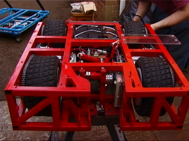 | 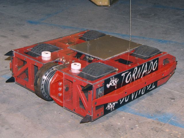 |
This technique was most famously used by Tornado. You can see the red box section chassis with all components attached using various brackets. Typical sizes for box section were around 25mm square with a 2mm wall.
This is still a viable technique to build robots however there are a number of downsides. The weakest point of your armour are the bolts holding it on. You could weld the panels on but then this means that you are wasting weight with the box section chassis. It can also take a great deal longer to create a box chassis and then cut all the panels for it.
Formula one cars used to use the same manufacturing technique however they moved to a monocoque design. So have modern robots. A monocoque means that your armour and chassis are one and the same.
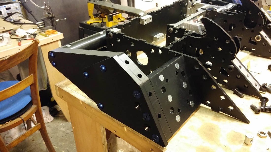
As you can see above, this is the technique we used with PP3D. All the panels that form the robots body are both the armour and the chassis. All the pieces were cut by a laser cutting company and designed to slot together with interlocking tabs. These were then all welded together using our stick welder (we didn't have any gas available at the time for the TIG welder).
There are a number of advantages to this system. It is much more weight efficient as you can make the panels at the front thicker than those at the rear to move the armour to where it's required. You can make the shape much more efficient and it's much quicker to come together. It also results in a far stronger structure.
 | 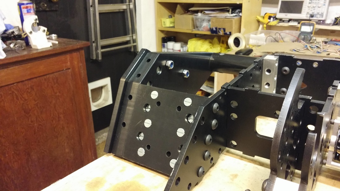 |
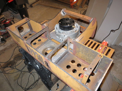
The third method used is a bolted together bulkhead style design as shown with the insides of Pulsar above. This method generally starts with a base onto which bulkheads are bolted. These form an inner structure that the armour is then attached to. Generally using this method the armour is made from as few pieces as possible to increase strength. Another notable use of this technique is Terrorhurtz which survived an onslaught from Carbide with only a few scratches! The resultant chassis is strong, not as strong as a welded chassis but you have the advantage that it can be taken apart and individual pieces replaced.
The majority of modern robots use a monocoque or bulkhead system of some variety with every robot that made it to the final 6 of Robot Wars 2016 using the techniques. We would therefore recommend incorporating it into your own designs.
The majority of modern robots use a monocoque or bulkhead system of some variety with every robot that made it to the final 6 of Robot Wars 2016 using the techniques. We would therefore recommend incorporating it into your own designs.
Materials
For this section we will look at each material available to you in turn and discuss where they have been used successfully and otherwise in the past.
Mild Steel
Mild steel is a great material. It comes in a whole range of shapes and profiles and easy to machine with handheld tools and a bit of patience. You can also easily weld it with a cheap welder from Aldi or Lidl for around £40, some welding rods (ebay is a good source) and a bit of practice. When using an arc welder, make sure that your rods are kept dry. If they get wet being stored in the garage or shed an hour in the oven at 120 deg C will dry them out. If you have access to MIG or TIG welding equipment then this can easily be welded with either.
It's very useful for making internal brackets for the robot. We wouldn't advise using it for armour though as there are far better materials available for not much more in price.
If you do a quick google search chances are you will find a number of suppliers relatively close to you and the majority will deliver. We'd always advise getting a few quotations as prices can vary between suppliers. We would also recommend giving any exposed mild steel a quick spray with some WD40 and a wipe down with a rag as even if it is stored inside in the garage or shed as it will gradually form surface rust.
Stainless Steel
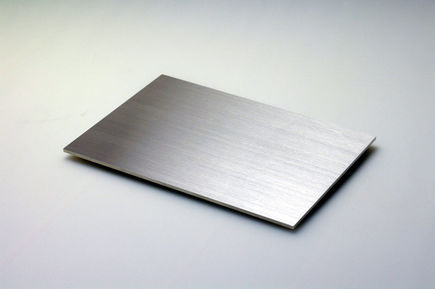
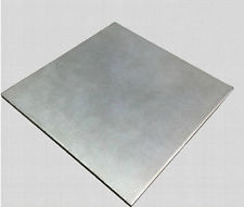
Stainless steel as the name says, doesn't stain or tarnish easily. It won't rust up in the same way that mild steel will. It is stronger than mild steel and requires a bit more patience to machine. It is available in a more limited range of shapes and profile but can still be found in plate and sheet. Due to the extra costs involved with stainless steel for a relatively soft material there isn't much we would recommend using it for.
Hardox, Weldox, Armox, RAEX.......
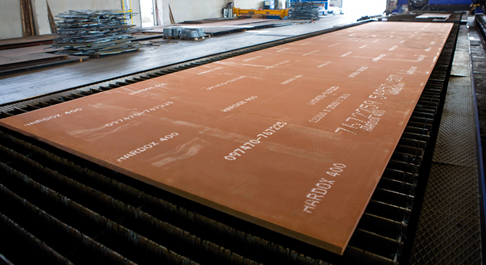 |  |
These are the materials you will have heard all about from the latest series of Robot Wars and that's because they are the go to materials for a lot of robot builders. They are all iron based like the steels mentioned previously however they are designed to be used as wear plates. Wear plate materials are designed to be used in industrial applications where they are subjected to heavy wear such as JCB digger buckets and truck bodies used to transport stone in quarries.
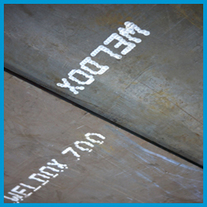
Hardox is the standard go to of these materials. It is actually a trade name of the Swedish company SSAB and so other companies have equivalent products such as RAEX. Weldox is a material from SSAB which as it's name suggests is better for welding. In actual fact it is merely better at retaining it's properties during heavy welding processes. Essentially all the wear plate materials begin to lose the material properties when subjected to high amounts of heat. It is also not available in the same thin sheets thicknesses that hardox is available in. Typical armour on a heavyweight is anywhere from 3mm to 10mm depending on the location on the robot.
Armox is the military grade equivalent that is used in armour for military vehicles. Due to this it is far more expensive and more difficult to get a hold of than hardox and weldox. It rarely makes sense to use it.
When ordering hardox you will see a number appear in the description. This will be 400, 450, 500 or 600. This refers to the brinell hardness of the material. We'd recommend having a read up on this property via google to properly understand it but essentially the higher the number, the harder the material. All grades of hardox will stand up to the majority of robot applications. The higher grades are far more difficult to machine and are typically not available in the thinner thicknesses that we require.
When it comes to machining hardox, it can be welded with stick arc, TIG and MIG using standard filler material as you would with mild steel. Cutting and shaping can be carried out with an angle grinder with a disc suitable for ferrous material. Drilling can get a little more difficult. We would recommend using either cobalt drill bits or bosch all purpose drill bits. Best to use a pillar drill with as slow a speed as possible. All of the wear plate materials can be laser cut, water cut and plasma cut. We used a mixture of laser and plasma cutting in PP3D. We will discuss manufacturing in more detail in a future post.
Titanium
Titanium is a great material when used in the right application. It is exceptionally expensive but very strong. The easiest way to tell if you are working with a piece of titanium is to touch a grinding disc to it. Titanium will give you a characteristic bright white spark whereas steels give a yellow orange spark. With experience you can also tell due to the weight of the piece. Titanium has a density just over half of steel.
There are a number of grades of titanium. The most useful to us is grade 5 titanium. This is the grade that the majority of titanium is manufactured in worldwide. It has great strength characteristics and is well suited to armour applications.
It can and has been used for armour in the past but sourcing it without breaking the bank can be a real issue!
Machining it is an interesting affair. You can use an angle grinder to cut and shape but just be aware that the sparks are hotter and will set materials on fire more readily. We have in the past had titanium fires from excess material when turning it on a lathe. The only thing you can really do is to walk away as a titanium fire creates it's own oxygen and will keep burning intensely. When drilling use sharp HSS bits and flood the area with coolant. Titanium tends to gum up when drilling if your drill bits aren't sharp. If you want to tap a thread into it, use a high quality spiral tap. Otherwise you will likely snap the tap. We will discuss this further in a future post and how it nearly ruined our chances of getting on Robot Wars!
Aluminium
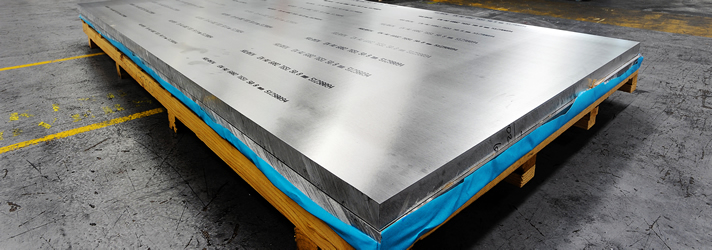
Aluminium is an excellent material to use in the construction of combat robots. It's exceptionally light, easy to work with, strong and it won't break the bank. It's best used in internal applications. Everything from bulkhead supports through to pneumatic components can all be made from aluminium. It shouldn't be used as armour as it is far too soft for that application.
Aluminium can be found in a large number of grades. Some are easier to machine, others are easier to weld and some are stronger than others. We would recommend researching the various grades before purchasing.
In PP3D we used aluminium in the custom bearing block housings that we machined up to support the disc shaft.
It can be machined with a wide range of hand tools and is very easy to drill, turn and mill. It can be welded but you will need special equipment to do so. Aluminium can be tapped and will hold a thread which makes it easy to use bolts in the internal construction of a robot.
Nylon
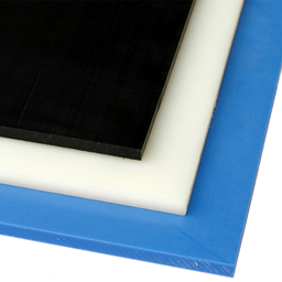
Plastics are an interesting topic in combat robots. They can be very useful due to their very low density resulting in lightweight parts but they have to be used in the right ways. Nylon is a material that is very good for structural applications. It is a slippy plastic that is very difficult to bond with adhesives but will hold a thread and so can be bolted together. You can also "weld" it with special equipment which melts the plastic to bond it together.
Nylon has been used successfully in featherweight robots for years however it has still to be fully proven in a heavyweight robot. We wouldn't recommend it for armour.
Nylon has been used successfully in featherweight robots for years however it has still to be fully proven in a heavyweight robot. We wouldn't recommend it for armour.
HDPE
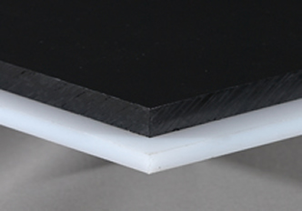
HDPE is a softer plastic which works well in armour applications. It's lightweight but very good at absorbing huge amounts of energy which makes it good against spinners. It is easy to machine with basic woodworking tools and is very cheap. It won't however hold a thread for bolts and so insert nuts should be used or it should be bolted together onto another structure.
This was the material that Gabriel was made from in the recent series of Robot Wars.
This was the material that Gabriel was made from in the recent series of Robot Wars.
Polycarbonate
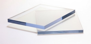
A clear plastic that was used a lot in the old days of Robot Wars. There are various reasons why but essentially we wouldn't recommend using it in a new build.
In summary there are a variety of options available when it comes to chassis design. All have good points and bad points. The design of the chassis that you use will depend on what experience, tooling and equipment you have available and also the weapon you plan to incorporate. With materials again there are a huge range available but you don't necessarily have to have a huge budget to build a competitive machine. The chassis on PP3D was one of the cheaper elements and was assembled using a stick arc welder! If you have any questions about a design idea then by all means drop us a line and we would be only too happy to discuss through your options.
Want to support PP3D and get your name on our new discs for a second series of Robot Wars!? Then check out our kickstarter
https://www.kickstarter.com/projects/583580427/pp3d-upgrades-for-series-2-of-robot-wars
Want to support PP3D and get your name on our new discs for a second series of Robot Wars!? Then check out our kickstarter
https://www.kickstarter.com/projects/583580427/pp3d-upgrades-for-series-2-of-robot-wars

 RSS Feed
